
A smart lock is a mixed-load system
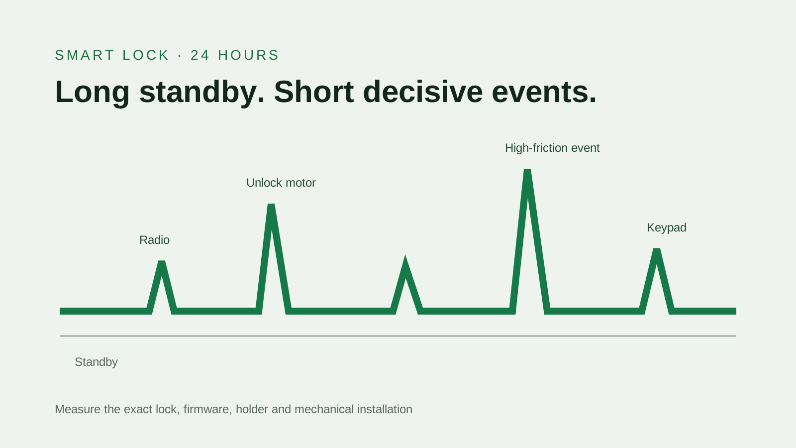
A smart lock may spend most of the day waiting, yet the moments that decide whether it opens are short and demanding. The controller wakes, a radio exchanges data, indicators light and a motor moves the mechanism. Standby current influences how quickly stored energy is consumed between operations. The radio and motor events test whether terminal voltage remains above the lock's operating threshold. A battery can therefore look satisfactory in a low-current capacity test and still produce an early warning, slow motor or failed opening in a particular lock. The useful engineering model includes both the quiet hours and the short events.
Begin with the exact device manual and product revision. Battery advice is not consistent across all locks: the reviewed Schlage Control guide specifies four high-quality AA alkaline batteries for that product. Other products may use different primary cells or a proprietary rechargeable pack. That model-specific instruction takes priority over a general claim about rechargeable chemistry. If a buyer wants to evaluate an alternative, the lock manufacturer must allow it or the buyer must accept responsibility for a controlled validation and support policy. A battery supplier cannot turn a category-level use case into universal compatibility.
| State | Measurement | Risk if omitted |
|---|---|---|
| Standby | Average and maximum sleep current over time | Replacement interval estimate is misleading |
| Radio event | Current, duration and frequency for each protocol event | Remote or keypad activity is underrepresented |
| Motor event | Peak current, minimum voltage and movement time | The lock can fail at the moment it must move |
| Warning state | Trigger voltage and operations remaining | Users receive too little or misleading notice |
The door and mechanism change the electrical result
Motor demand is not fixed by the electronics alone. Door alignment, latch friction, temperature, installation torque and wear can change how much work the motor performs. A laboratory lock on a loose fixture may draw less than a lock installed on a door with side load at the bolt. The sample plan should therefore define at least a normal mechanical condition and a credible high-friction condition approved by the lock designer. Measure current and terminal voltage while the mechanism moves in both directions. If the motor time increases as cells discharge, record that trend rather than reducing the result to one runtime number.
Contacts also deserve attention. Multiple AA cells create several interfaces between cell ends, springs and the electronics. Surface contamination, reduced spring force or a cell that fits differently can add resistance. A brief voltage dip at the controller may come from the cell, the holder or both. Measure at the cell pack and at the device input when possible. Inspect compartment dimensions and polarity features against the exact candidate cell. This is particularly important when moving between cell constructions that share an AA label but may differ within the permitted physical envelope.
- Test with the production latch, door alignment and firmware
- Define a repeatable high-friction condition
- Measure voltage at both the pack and the electronics when practical
- Inspect cell fit, spring force and contact cleanliness
Low-battery warning is part of compatibility
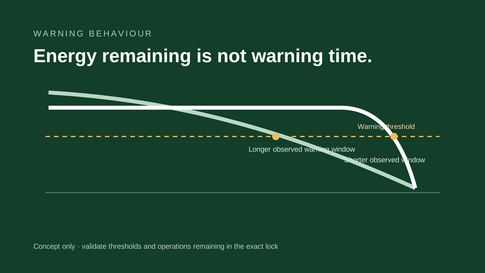
Many devices infer remaining battery life from voltage, load response, a selected battery profile or a combination of signals. Different chemistries do not follow identical discharge shapes. A gradually declining source can cross a warning threshold with a useful amount of operation remaining. A regulated source may hold a stable output for much of its discharge and then approach an internal shutdown. If the lock expects a gradual decline, the user may see a warning that is early, late or inconsistent with actual operations remaining. Stable voltage during use is not enough to prove that the warning system is safe or convenient.
Define warning acceptance before the battery comparison. Record the first warning, any escalating warning, mobile-app notification and the point where motor operation is refused. Count successful operations remaining under the agreed mechanical condition and temperature. Check what happens after the lock rests, because voltage recovery can temporarily clear an alert. The right target is not the largest possible count after warning. It is a predictable service window that supports the product's maintenance and emergency-access plan. If the lock cannot provide that window with a candidate chemistry, the candidate may be unsuitable even when total energy is attractive.
Chemistry changes maintenance as well as voltage
A primary-cell program can be attractive when the device manual specifies it, the replacement interval is long and property managers prefer a simple scheduled swap. Ni-MH may suit products that explicitly support it and installations where charging logistics are controlled, but the nominal-voltage profile and self-discharge behaviour must fit the lock. A regulated rechargeable lithium AA offers a different output and charging workflow; it also requires exact-model transport documentation and careful review of end-of-discharge behaviour. A proprietary pack can allow tighter monitoring and charging control, while increasing dependence on the device maker's pack and charger system.
Operational ownership often decides the shortlist. A homeowner, hotel, rental portfolio and commercial access-control operator have different tolerance for charging, mixed cells and unscheduled visits. Define who receives the alert, who carries spares, how replaced cells are handled and whether a fixed maintenance interval is required even when the indicator still shows capacity. Do not mix old and new cells or unverified cell types in a series set. Document the approved model and replacement procedure in service instructions. A technically compatible cell program can still fail commercially when no one owns the charging and replacement process.
| Decision | Questions to answer | Evidence to retain |
|---|---|---|
| Device permission | What does the exact lock manual allow? | Manual revision and approved battery list |
| Warning | How and when does the lock alert? | Firmware version and operations-after-warning test |
| Maintenance | Who replaces or charges cells and when? | Service procedure and spare-set policy |
| Environment | What temperatures and mechanical loads occur? | Installation envelope and validation results |
| Transport | Does the selected model contain lithium? | Exact-model test summary and route-specific shipping pack |
Build a validation matrix around failure modes
A useful matrix varies only the factors that can change the decision. At minimum, include the exact cell model, lock and firmware revision, starting state, ambient condition, normal and high-friction operation, radio activity and warning state. Define pass criteria for successful movement, controller reset, motor time, communication and alert behaviour. If service life is a target, translate expected daily events into a repeatable cycle, but avoid presenting accelerated bench cycling as calendar life without a justified model. Standby energy, temperature and self-discharge continue between motor events and need separate treatment.
Record every sample and anomaly. If one lock fails, determine whether the cause follows the cell, holder, mechanism or device. Avoid averaging away a failure that would prevent entry. The acceptance decision should state the operating envelope and the exact cell revision. If the product team changes firmware thresholds, motor drive, gearbox, holder or enclosure, reassess the relevant rows. This is also the point to align claims: a measured result under defined conditions can support an internal design decision, but a public claim such as a number of months requires a representative-use method and review outside a simple sourcing comparison.
- Lock and firmware revision
- Normal and defined high-friction mechanical condition
- Standby, radio and motor event sequence
- Warning trigger and successful operations remaining
- Temperature points relevant to the installation
- Failure classification and retest rule
Design the failure and replacement policy before launch
A lock is not an ordinary convenience device. The product program should state what happens when energy becomes insufficient: how early the user is warned, whether an external emergency-power option exists, how mechanical access works and who is responsible for replacement. Those are lock-system decisions, not features a cell can provide. Battery selection should be judged against that plan. A candidate that provides excellent energy but an unacceptable alert window can create more service risk than a lower-energy option with predictable warning behaviour.
Scheduled replacement can be sensible in managed properties even when cells have capacity remaining. The interval should be derived from validated use assumptions with margin for event frequency, temperature, radio conditions and mechanical variation. Store spares according to the cell maker's guidance and prevent unapproved substitutions. When support teams receive an early-drain report, collect the lock model, firmware, installation condition, event history, battery model, lot and replacement date. That evidence distinguishes a cell issue from alignment, radio, firmware or maintenance problems and prevents a generic instruction to try a different battery from becoming the entire diagnostic process.
- Define warning ownership and escalation
- Provide a documented emergency-access path
- Set a scheduled replacement rule where operations require it
- Capture model, lot, firmware and mechanical condition in field reports
The smart-lock sourcing brief we would ask for
Send the exact lock model, manual and firmware revision; number and arrangement of cells; compartment drawing; permitted battery types; standby current; radio protocol and event frequency; motor peak and duration; device voltage window; warning thresholds; required service interval; operating temperature; installation type; target markets; shipment method and annual volume. If those measurements are not yet available, identify which are estimates and schedule them into sample validation. A clear unknown is safer than a precise-looking number with no method behind it.
PUJIMAX can use that brief to compare current published models and identify the model-level documents available. The output should be a shortlist with explicit open questions, not a universal recommendation. The lock team then validates the candidate in the production-intent device and approves its warning and replacement behaviour. If the manual excludes the chemistry, resolve that with the lock manufacturer rather than expecting a battery test to override the instruction. This sequence keeps device authority, supplier evidence and operational policy in their proper places.
| Input group | Required detail | Why it matters |
|---|---|---|
| Device identity | Model, firmware, manual and holder revision | Prevents category advice from replacing exact instructions |
| Electrical profile | Standby, radio, motor peak, duration and cutoff | Defines output and energy requirements |
| Mechanical envelope | Normal and high-friction installation | Captures load variation at the motor |
| Warning policy | Thresholds, alerts and operations remaining | Tests whether the maintenance window is usable |
| Commercial program | Market, volume, replacement owner and shipment | Connects the cell choice to documents and operations |
Sources and evidence checked
- Nickel-metal hydride application and design criteriaVARTA Microbattery · checked 2026-08-28
- eneloop voltage and device-use FAQPanasonic Energy · checked 2026-08-28
- Control Smart Locks user guideSchlage · checked 2026-08-28
Frequently asked questions
Are rechargeable AA batteries suitable for every smart lock?
No. Follow the exact lock manual. If an alternative is permitted, validate its voltage, motor-event and warning behaviour in that lock and firmware revision.
Why can a lock show low battery earlier than expected?
The alert may respond to voltage profile, load response, temperature or a battery-type assumption. The holder and mechanical load can also contribute to voltage drop.
Can a stable 1.5 V output guarantee a correct warning?
No. Stable output and warning behaviour are different questions. The lock's algorithm must be tested through the candidate cell's end-of-discharge behaviour.